Saturday, July 21, 2018

PURPOSE OF PIPE SUPPORTS: A small article for beginners

For proper working of the piping system it has to be supported properly. The major purpose of pipe support is described below:
  • TO SUPPORT WEIGHT OF PIPE-DURING OPERATION & TESTING:
Supports are required to support the line during all conditions i.e. during operation as well as during testing. In case of vapour line this difference will be very large due to hydro testing. Supports should be designed for this load (unless otherwise decided in the project). Sometimes line is capable of having longer span but load coming on the support may be very large (especially with large diameter pipe lines). Then to distribute the load uniformly, more number of supports should be provided with smaller span. Note: 1. it may be noted that during testing condition there is no thermal load. 2. All spring supports are locked during testing.
  • TO TAKE THE ‘THERMAL OR EXPANSION LOAD’:
Whenever thermal expansion is restricted by support, it introduces additional load on the support. Support restraints must be designed to take this load in addition to all other loads.
  • TO TAKE THE ‘ OCCASIONAL EARTH QUAKE LOAD’:
The earthquake is normally associated with horizontal acceleration of the order of 1 to 3 m/sec2. This is around 10% to 30% of the gravitational acceleration and introduces horizontal force of about 10 to 30% of the vertical load (or supported mass). While designing support this should be taken care.
  • TO TAKE ‘HYDRAULIC THRUST IN PIPING’ :

The hydraulic thrust (Fig. 1) in the pipeline is present at certain point such as pressure reducing valve, relief valve, bellows etc.
If the control valve has large pressure differential and line size is more, then this force can be very high.

Figure showing thrust force

Fig. 1: Figure showing thrust force
The support should be provided and designed to take this load, otherwise this will load the piping system and may cause failure.
  • TO ABSORB ‘VIBRATION OF PIPING SYSTEM’ :
When the pipe is subjected to moving machinery or pulsating flow or very high velocity flow, pipe may start vibrating vigorously and ultimately may fail, particularly if span is large. To avoid this it may be required to introduce additional supports at smaller span apart from other requirements. It may not take axial load, but must control lateral movements.
Wind introduces lateral load on the line. This load is considerable especially on large diameter pipes and increases as line size is increased. This load tends to sway the line from its normal position and line must be guided properly against it to avoid any kind of malfunction. In case of large diameter overhead lines, supported by tall support extended from floor, wind load introduces large bending moment and should be considered critically.
  • TO SUPPORT THE SYSTEM DURING ‘TRANSIENT PERIOD OF PLANT AND STANDBY
CONDITION: Transient condition refers to the start-up or shutdown condition in which one equipment may get heated up faster and other one get heated slower. Due to this the expansion of one equipment which in normal operation will get nullified, may not get nullified and exert thermal load on supports.


Operating- Standby Condition
Fig. 2: Operating- Standby Condition
Standby condition is also similar. If there are two pumps, one being standby and both connected in parallel (as shown), design and operating temperature of both the connections will be same. But the expansion of two parallel legs will not be nullified because at a time only one leg will be hot and another being cold.
  • TO HAVE ‘NOISE CONTROL’ :
In most of the plants, noise is resulting from vibration and if such vibrations are controlled, noise is reduced to great extent. In such lines, between clamp (i.e. support) and pipe, asbestos cloth is put to absorb vibration and avoid noise.
Noise due to pulsating flow can be reduced by using a silencer in the line. Still if it is not below acceptable level acoustic enclosure may be used. Insulation over line also helps in reducing the noise.
  • TO SUPPORT THE SYSTEM DURING ‘MAINTENANCE CONDITIONS’ :
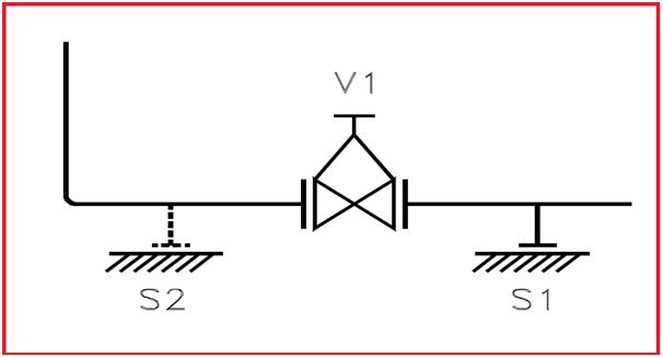
When for maintenance certain equipment or component like valve is taken out, remaining system should not be left out unsupported.


Figure showing support addition during maintenance activities
Fig. 3: Figure showing support addition during maintenance activities
Referring to the FIG-3, support ‘S1’ will be sufficient but when valve ‘V1’ is taken out for maintenance there will not be any support for vertical leg. Therefore second support ‘S2’ may be required to take care of such condition.
  • TO SUPPORT THE SYSTEM DURING ‘SHUTDOWN CONDITIONS’ :
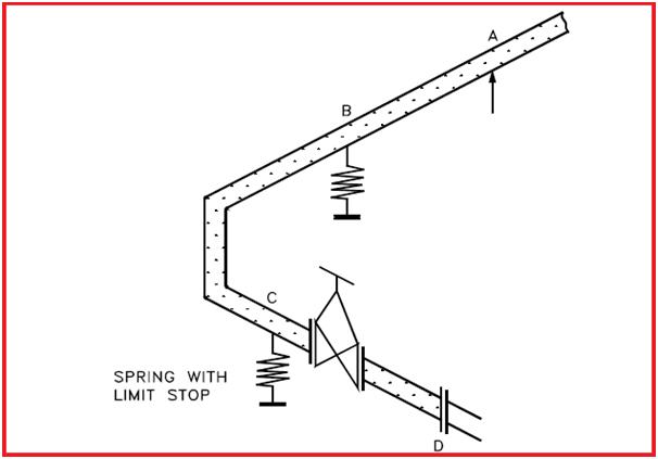
In shutdown condition all equipment may not be in the same condition as in operating condition. For example, refer the pump discharge line in FIG-4, Point A is resting, Point B & C are spring supports and Point D is the pump discharge nozzle. The springs are, designed based on weights considering the weight of fluid as well as pipeline and thermal movements. But during shutdown condition the fluid may be drained and the pipe becomes lighter. Hence the spring will give upward reaction and shall load the nozzle ‘D’ beyond permissible limit.


Use of Limit elements in spring during shut down
Fig. 4: Use of Limit elements in spring during shut down
In this case a limit stop is used which will not allow the Point C to move up above horizontal level. (However it will allow downward movement during operating condition).
  • TO SUPPORT THE SYSTEM FOR ERECTION CONDITIONS :
Erection condition can be different than the operating condition which should be considered while designing supports.
For example for normal operation a long vessel supported by three supports, S1, S2 & S3 is shown in FIG-5. If support S2 is higher, than all load will act at S2 only. During erection if level of S2 is lower than entire load will be divided into two supports S1, S2 only. Therefore foundation of S1, S2 & S3 should be capable of taking such conditions.


Vessel supported at three supports.

Fig. 5: Vessel supported at three supports.

A pipe line supported by S1, S2 & S3 taken from vessel is shown in above FIG – 6. During operation there will be no weight at S2 & S3 (as it is only guide), but wind condition will be there. Loads due to such conditions must be considered while designing the supports.


Pipe supported from vessel cleats.
Fig. 6: Pipe supported from vessel cleats.

TO REDUCE VIBRATION AMPLITUDES.

Piping Stress Job Interview questions for you: Part 1

The following list will provide few interview questions asked in different interview for a Piping Stress Engineer post. Hope you will be able to find the answers from ASME B 31.3 and any piping stress text books or from piping hand book. In case you could not find out a specific answer reply in comments section. This is the part one of the collection. Keep checking the website regularly for other parts.
1) How to make critical line list or flexibility log? How will you decide critical line list with help of ASME B31.3?
2) How to decide Stress critical systems for analysis using Caesar II?
3) Which lines can be eliminated from formal Stress analysis?
4) Can you make a typical Sketch & supporting for column piping? How to decide how many load bearing clip supports to be used?

5) Draw a typical Sketch & supporting arrangement for tank farm piping? How tank Piping analysis is different from normal pressure vessel connected piping system analysis?
6) What is SIF? Formulas for In plane, outplane sif for elbow (B31.3)?
7) Value of sif, flexibility factor for Bend?
8) What are the necessary documents required for stress analysis?
9) Why a Spring hanger is used? Can you write the formula for spring HL, CL & variability?
10) What are the different types of supports used in piping systems?
11) What do you know about Expansion joints and thier types? When these come into picture?
12) What are the normal types of load cases? Write the load cases for a typical stress system using static method of seimic and wind?
13) What is slug flow? What parameters are required to calculate Slug force?
14) What are the dynamic restraints? What is snubber and when do you use a snubber?
15) What is the minimum swing allowed in top mounted hanger? What will you do if that amount exceeds in a typical piping system?
16) What is cold pull and why it is used?
17) What is difference between Variable Hanger and Constant Hanger? What is the variability of Constant Spring hanger?
18) What are the inputs required for stress analysis? What do you check in Caesar analysis of a piping system?
19) What do you mean by the term “liberal stress”?
20) What is hot-cold philosophy for pump? Have you heard the term Pump alignment?

Tuesday, June 26, 2018

Stress Analysis of GRP / GRE / FRP piping system using Caesar II: Part 2 of 2

Continued from part 1…. Click here to go to the part 1…

Modelling of Bend and Tee Connections:
  • Modelling of bends is a bit different as compared to CS piping. Normally bend thicknesses are higher than the corresponding piping thickness. Additionally you have to specify the parameter, (EpTp)/(EbTb), which is located at the Bend auxiliary dialogue box.. This value affects the calculation of the flexibility factor for bends.
  • When you click on SIF and Tee box in Caesar II spreadsheet, you will find that only three options (Tee, Joint and Qualified Tee) are available for you . Each type has their own code equation for SIF calculation. Use the proper connection judiciously. It is always better to use SIF as 2.3 for both inplane and outplane SIF to adopt maximum conservative approach.
  • Load Cases for Analysis:
    ISO 14692 informs to prepare 3 load cases: Sustained, Sustained with thermal and Hydro test. So accordingly the following load cases are sufficient to analyse GRP piping system
    1. WW+HP …………………….HYDRO
    2. W+T1+P1 …………………..OPERATING-DESIGN TEMPERATURE
    3. W+T2+P1 …………………..OPERATING-OPERATING TEMPERATURE
    4. W+P1 ………………………..SUSTAINED
    The expansion load cases are not required to create as no allowable stress is available for them as per the code.
  • While preparing the above load cases you have to specify the occasional load factors for each load case in load case options menu. ISO 14692 considers hydro test case as an occasional case. In higher versions of Caesar II software (Caesar II-2016 and Caesar II-2017) these load factors are taken care by default. So you need not enter the values. The option of these value entry will be available only if you define the stress type as occasional for those software versions.
  • The default values of occasional load factors are 1.33 for occasional case, 1.24 for operating case and 1.0 for sustained case. This occasional load factors are multiplied with system design factor (normally 0.67) to calculate the part factor for loading f2.
    For aboveground GRP piping the above load cases are sufficient. But if the Line is laid undeground then two different caesar II files are required. One for sustained and operating stress check. And the other for hydrotesting stress check as the buried depth during hydrotesting is different from the original operation. Also buried depth may vary in many places. So caesar II modelling should be done meticulosly to take care exact effects.the long lengths into shorter elements to get proper results. Element length of 3 m or less is advisable. Sometimes buried model contains slope, Those sloved are required to model properly to get accurate results.
    Output Results:
    Both stress and load data need to be checked for GRP piping.  Normally the stresses are more than 90% (Even sometimes it may be as high as 99.9%).

Stress Analysis of GRP / GRE / FRP piping system using Caesar II: Part 1 of 2

GRP products being proprietary the choice of component sizes, fittings and material types are limited depending on the supplier. Potential GRP vendors need to be identified early in design stage to determine possible limitations of component availability. The mechanical properties and design parameters varies from vendor to vendor. So it is utmost important that before you proceed for stress analysis of such systems you must finalize the GRP/FRP/GRE vendor. Several parameters (Fig. 1) for stress analysis have to be taken from vendor.
Stress analysis of GRP piping system is governed by ISO 14692 part 3. The GRP material being orthotropic the stress values in axial as well as hoop direction need to be considered during analysis. The following article will provide a guideline for stress analysis of GRP piping system in a very simple format.
Inputs Required for Analysis:
For performing the stress analysis of a GRP piping system following inputs are required:
  • GRP pipe parameters as shown in Fig. 1.
  • Pipe routing plan in form of isometrics or piping GA.
  • Analysis parameters like design temperature, operating temperature, design pressure, fluid density, hydro test pressure, pipe diameter and thickness etc.
Modelling in Caesar II:
Once all inputs as mentioned above are ready with you open the Caesar II spreadsheet. By default Caesar will show B 31.3 as governing code.
  • Change the default code to ISO 14692.
  • Change the material to FRP (Caesar Database Material Number 20) as shown in Fig. 2. It will fill few parameters from Caesar database. Update those parameters from vendor information.
  • Enter pipe OD and thickness from vendor information.
  • Keep corrosion allowance as 0.
  • Input T1, T2, P1, HP and fluid density from line list.
  • Update pipe density from vendor information sheet, if vendor does not provide density of pipe then you can keep this value unchanged.
  • On the right side below the code, enter the failure envelop data received from vendor.
  • Enter thermal factor=0.85 if pipe is carrying liquid, enter 0.8 if the pipe carries gas.
  • After you have mentioned all the highlighted fields proceed modelling by providing dimensions from the isometric/piping GA drawing. Add supports at proper location from isometric drawing.
  • Now click on environment button and then on special execution parameter.
  • Enter the GRP/FRP co-efficient of thermal expansion received from vendor
  • Calculate the ratio of Shear Modulus and Axial modulus and input in the location.
  • In FRP laminate keep the default value if data is not available.
  • After the above changes click on ok button.
  • While modelling remember to change the OD and thickness of elbows/bends.


Saturday, June 23, 2018

Must have Load cases for stress analysis of a typical piping system using Caesar II

The main objectives of stress analysis is to ensure
A. Structural Integrity (Design adequacy for the pressure of the carrying fluid,Failure against various loading in the life cycle and Limiting stresses below code allowable.)
B. Operational Integrity (Limiting nozzle loads of the connected equipment within allowable values, Avoiding leakage at joints, Limiting sagging & displacement within allowable values.)
C. Optimal Design (Avoiding excessive flexibility and also high loads on supporting structures. Aim towards an optimal design for both piping and structure.)
To meet these objectives several load cases are required during stress analysis. This article will guide all the beginners with the methodology to build several load cases which will be required for stress analysis.
In this article we will use following notations for building load cases:
WW=water filled weight of piping system,
HP=Hydrotest Pressure,
insulation,
P1=Internal Design pressure,
T1=Operating temperature,
T2=Maximum temperature,
T3= Minimum temperature,
WIN1, WIN2, WIN3 AND WIN4: wind loads acting in some specific direction,
U1, U2, U3 AND U4: uniform (seismic) loads acting in some specific direction.
While analysis at a minimum the stress check is required for the below mentioned cases:
a. Hydrotesting case: Pipelines are normally hydrotested before actual operation to ensure absence of leakage. Water is used as the testing medium. So during this situation pipe will be subjected to water weight and hydrotest pressure.
Accordingly our first load case in Caesar II will be as mentioned below
1.                    WW+HP                          HYD
b. Operating case: When operation starts working fluid will flow through the piping at a temperature and pressure. So accordingly our operating load cases will be as mentioned below:
2.            W+T1+P1                OPE                   for operating temperature case
3.            W+T2+P1                OPE                   for maximum system temperature case
4.            W+T3+P1                OPE                   for minimum system temperature case
c.  Sustained Case: Sustained loads will exist throughout the plant operation. Weight and pressure are known as sustained loads.  So our sustained load case will be as follows:
5.             W+P1                           SUS
d. Occasional Cases:  Piping may be subjected to occassional wind and seismic forces. So to check stresses in those situations we have to build the
following load cases:
6.                W+T1+P1+WIN1                       OPE                      Considering wind from +X direction
7.                W+T1+P1+WIN2                       OPE                      Considering wind from -X direction
8.                W+T1+P1+WIN3                      OPE                      Considering wind from +Z direction
9.                W+T1+P1+WIN4                       OPE                     Considering wind from -Z direction
10.              W+T1+P1+U1                            OPE                      Considering seismic from +X direction
11.              W+T1+P1-U1                              OPE                      Considering seismic from -X direction
12               W+T1+P1+U2                            OPE                      Considering seismic from +Z direction
13               W+T1+P1-U2                              OPE                      Considering seismic from -Z direction
While stress analysis the above load cases form load case 6 to load case 13 is generated only to check loads at node points.
To find occasional stresses we need to add pure occassional cases with sustained load and then compare with code allowable values. Following sets of  load cases are built for that purpose.
14.                 L6-L2                      OCC                         Pure wind from +X direction
15.                 L7-L2                      OCC                         Pure wind from -X direction
16.                 L8-L2                      OCC                         Pure wind from +Z direction
17.                 L9-L2                      OCC                         Pure wind from -Z direction
18.                 L10-L2                    OCC                        Pure seismic from +X direction
19.                 L11-L2                    OCC                         Pure seismic from -X direction
20.                L12-L2                    OCC                         Pure seismic from +Z direction
21.                 L13-L2                    OCC                         Pure seismic from -Z direction
22.                 L14+L5                  OCC                         Pure wind+Sustained
23.                 L15+L5                  OCC                         Pure wind+Sustained
24.                 L16+L5                  OCC                         Pure wind+Sustained
25.                 L17+L5                  OCC                         Pure wind+Sustained
26.                 L18+L5                  OCC                         Pure seismic+Sustained
27.                 L19+L5                  OCC                         Pure seismic+Sustained
28.                 L20+L5                  OCC                        Pure seismic+Sustained
29.                 L21+L5                   OCC                       Pure seismic+Sustained
Load cases from 22 to 29 will be used for checking occasional stresses with respect to code B 31.3 allowable (=1.33 times Sh value from code). Use scalar combination for load cases 22 to 29 above and algebraic combination for others as shown in figure attached below:
load cases
e. Expansion Case: Following load cases are required for checking expansion stress range as per code
30.                 L2-L5                     EXP
31.                  L3-L5                    EXP
32.                 L4-L5                     EXP
33.                 L3-L4                    EXP                            for complete stress range
The above load cases (from 30 to 33) are used to check expansion stress
The above mentioned load cases are minimum required load cases to analysis any stress system. Out of the above load cases the load cases mentioned in point number 1, 5, and 22-33 are used for stress check. And load cases mentioned in point number 1 to 13 are used for checking restraint forces, displacements and nozzle load checking.
Few additional load cases may be required for PSV connected systems, Rotary equipment connected systems.
Seismic and Wind analysis may not be required every time. So those load cases can be deleted if the piping system does not fall under the purview of seismic and wind analysis by project specification.  However to perform wind and seismic analysis proper related data must have to be entered in Caesar II spreadsheet (Will be discussed in my future posts).
If the stress system involves use of imposed displacements (D) and forces (F) then those have to be added with the above load cases in the form of D1, D2 or F1, F2 as applicable.
It is a better practice to keep
1. Hydro and sustained stresses below 60% of code allowable
2. Expansion and occasional stresses below 80% of code allowable
3. Sustained sagging below 10 mm for process lines and below 3 mm for steam, two phase and flare lines
4. Design/Maximum displacement below 75 mm for unit piping and below 200 mm in rack piping.